How to Replace a Single-Pole Light Switch
If a switch doesn’t work, first make sure the problem is with the switch and not the light or device it’s supposed to power. Put a new bulb into the light fixture or plug a working lamp or other appliance into the switch-controlled receptacle to make sure the switch is faulty.
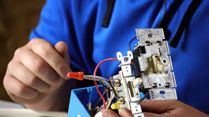
When you replace a switch, make sure you check the amp and voltage ratings on the back of the old switch. The new switch should have the same ratings. If you have aluminum wiring (the metal part of the wires looks silvery), be sure to get a replacement switch marked “CO/ALR.” Unmarked or CU/AL switches should be replaced with CO/ALR switches.
Here is how to replace or install an old single-pole light switch with new one:
- After shutting off the power to the switch, use a screwdriver to remove the plastic faceplate and to unscrew the existing switch from the electrical box.Pull the switch outward without touching any bare wires. Use an electrical tester to check the wires that go to the existing switch (or the new wires that are intended for the switch) so you can be sure they are not active.
Place one probe on the bare ground wire inside the box and touch the other probe on each of the wired screw terminals of the switch or the bare end of the black wire that will carry electricity to the switch. No voltage should register.
- Once you’re sure the power is off to the switch, use the screwdriver to remove the existing switch (if there is one) from its wires.
If the wires are connected to terminal screws, turn the screws counterclockwise to loosen them and unhook the wires. If the wires are pushed into terminal holes in the back of the switch, push a very small flat-bladed screwdriver into the slot next to the screw connection holes to release the wires.
- Straighten or, if necessary, clip off the very ends of the circuit wires you will be connecting to the switch. Use wire strippers to remove 1/2-inch of insulation from the wire ends unless the ends are already stripped.
- Loosen the green grounding terminal screw on the switch and, using needle-nose pliers, loop the bare or green grounding wire from the circuit clockwise around it, and tighten the screw to lock the wire in place.
Note: If the switch has its own grounding wire, twist the bare end together with the circuit’s grounding wire, using lineman pliers, and secure it with a copper compression sleeve or wire nut. Note: If you are using a metal box, include a grounding wire “jumper” from the ground wire connections to the box.
- If the switch has terminal screws, loop the circuit wires clockwise around the terminal screws in the same fashion and tighten the screws.
It does not matter which wire goes to which terminal. If the switch only has push-in terminal holes in the back, make sure that 1/2 inch of insulation is stripped from the end of each circuit wire, straighten each tip with lineman’s pliers, and push the wires into the terminal holes (again, note the brass and silver sides of the switch). Wiggle all the wire connections to make sure they are secure.
Note: If the new switch has short wires coming out of its body, use lineman’s pliers to twist together the bare end of the green wire clockwise with the circuit’s green or bare ground wire, and then secure the connection with a wire nut.
Then join the bare ends of the switch’s wires to the circuit wires, twisting clockwise, and secure them with wire nuts. Wiggle the wires to make sure the connections are secure.
- Mount the switch right side up. First, fold the wires behind the switch and carefully push the switch into the box. Next, align the switch vertically by adjusting the screws in the mounting slots.Also make sure the switch is flush with the wall. If it isn’t, shim it out using the break-off portions of the switch’s plaster ears or use special washers sold for shimming purposes. Screw the switch to the box.
- Screw the faceplate to the switch using the screws included with the faceplate.
Then turn the circuit back on. If the light still doesn’t work, the problem is in the wiring or the light fixture. See Light Fixtures Troubleshooting & Repairs.
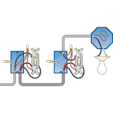
FIVE STEPS FOR 3 WAY LIGHT SWITCH WIRING:
- Turn off the correct circuit at your electrical panel.
- Add an electrical box for the second three-way switch in the basement. It’s likely you’ll also need to replace the existing switch box with a larger one to accommodate the extra wires for the 3 way switch.
- Feed a length of 14-3 type NM cable (or 12-3, if you’re connecting to 12-gauge wire) between the two boxes. The 14-3 cable has three insulated conductors: white, black and red (plus a bare ground wire).
- Connect the wires to the new three-way switches with ground screws using one of the two wiring diagrams (Fig. A or B). The switches will be identified by a label on the common terminal and/or the terminal screw will be a different color.
- Make sure to wrap black electrical tape around the ends of all white wires used as travelers between the three-way switches. If you have the setup shown in Fig. A, also wrap black tape around the white wire from the switch to the light. This way, both you and others will know these wires are “hot” and not neutral like most white wires.
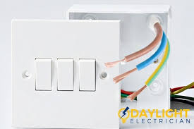
Caution: If you have aluminum wiring, call in a licensed pro who’s certified to work with it. This wiring is dull gray, not the dull orange that’s characteristic of copper.
Required Tools for this 3-Way Switch Project
Have the necessary tools for this DIY wiring a three way switch project lined up before you start – you’ll save time and frustration.
- 4-in-1 screwdriver
- Electrical tape
- Needle-nose pliers
- Non-contact voltage tester
- Utility knife
- Wire stripper/cutter
Required Materials for this 3 Way Switch Project
Avoid last-minute shopping trips by having all your materials ready ahead of time. Here’s a list.
- 14-3 or 12-3 cable
- Three-way switches (2)
Does it matter which black wire goes where when changing a light switch?
The black wire is the hot wire, the one you should never touch with the power on. Correction: never touch any wire with the power on, and use a meter to double check they are all off before touching anything.
Next, never do any wiring unless you completely understand the task at hand.If you have two black wires in the box one may be bringing power in, and the other leading it out. If that is all that is there then the switch can go between them in either order.
If you have anything else stop and get further help where you can post pictures and a better description of this spot. Properly you should have a black always hot wire bringing power in and a red wire going to the light. Red means the line may be switched.
Sometimes electricians go cheap and use black instead of red.
Light switch without ground
Will a light switch work with no ground wire? Usually. Here’s why you normally want a ground, and what your options are for a light switch without ground.
For a normal light switch, the ground is a safety feature, not necessary for operation. You can leave that screw unconnected if you don’t have a ground wire, or if you have the wire but no screw on the switch, you can ground the switch another way.
The purpose of a ground wire on a light switch
The green-colored screw in the upper left is for the ground wire. I don’t recommend it, but you can wire a light switch without ground if you have to.
Some occupancy-sensing automatic light switches need a ground wire, but traditional toggle-type switches do not. They can do their job just fine with or without ground.
With an ordinary toggle switch like the ones on the right, the ground wire is strictly a safety feature. If you flip a switch with wet hands, having a ground connection reduces the chance of you shocking yourself. It doesn’t guarantee it, but it does reduce the chances. That’s why a light switch without ground isn’t the best idea, but it can still work.
Going without a ground wire
If the light switch has a screw for a bare ground wire but your electrical box doesn’t have one, you’re OK just leaving that screw empty and connecting your other wires to the hot screws.
In many cases, especially in older houses with metal boxes, the metal box may be grounded even if you don’t have a ground wire. When you screw the light switch in, it will make contact with the box, and as long as the box is grounded, it will pick up ground that way. If the box isn’t grounded, the switch will still work. Just be sure to remember your mother telling you to dry your hands before turning off the lights.
Connecting a ground wire to a light switch without a ground screw
What if you have a really old light switch that doesn’t have a ground screw, but you do have a ground wire? It would be a good idea to just replace the switch with a newer one that does. A modern residential light switch costs less than $1.
If you can’t, connect the ground wire to the electrical box instead, assuming it’s a metal electrical box. If you can’t do that, or if your box is plastic, wrap one turn of the ground wire around one of the screws that secures the switch to the box. As long as the switch’s bare metal frame makes metal-to-metal contact with ground somehow, your light switch is grounded for safety.
All About Light Switch Wiring
Learn how to fix a faulty light switch with our guide to power-through and end-line switches.
Being a smart homeowner means knowing what is going on in your home and how it works—including the electrical elements. Behind your walls, there are wires running up and down that make it possible for a light switch on the first floor to turn on a tall chandelier hanging from the ceiling. While it might seem like magic, it’s just a matter of understanding how your light switch wiring works. Check out our comprehensive guide to learn the ins and outs of light switch wiring, including information on power-through and endline switches.
How Does Switch Wiring Work?
The way a light switch is wired depends on whether the power comes into the light box or the switch box first. If power comes into the switch box first, the neutral white line from the service panel and the white line that leads to the light are spliced together. The hot black wire from the power source travels through the switch and from there to the light. Flipping the switch interrupts the flow of electricity to the light, turning it off and on.
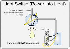
If the line carrying power comes into the light box first, the circuit must still be wired so the switch interrupts the black line. The white wire from the service panel is wired to one side of the light. The black wire is spliced to a black wire in a cable that runs to the switch. That cable’s white wire is also connected to the switch and runs back to and is connected to the light. Flipping the switch interrupts the flow of electricity, and the switch does its job.
Because the white wire from the switch to the light is now a hot wire, it must be marked to show it is hot. Wrap a piece of black electrician’s tape around it at both ends or color the end black with a marker to show that it carries power.
Power-Through Switches
With power-through wiring, power enters the switch box. The feed wire (the hot wire coming from the service panel) runs to the switch before it goes to the fixture. Two cables enter the switch box—one supplying power and one going to the fixture. The neutral wires are spliced, and a black wire connects to each switch terminal. (Ground wires are not shown.)
End-Line Switches
If power goes to the fixture first and then to the switch, you have “end-line” wiring. Only one cable enters the switch box, coming from the fixture. Here the white wire to the switch is marked black to indicate that it is hot. (Ground wires are not shown.)